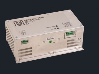
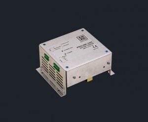
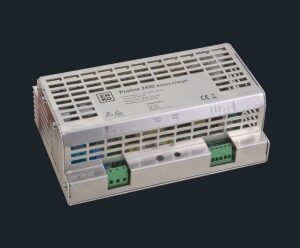
EBC 2410M can deliver continuous charging current of 10A into 24V battery system (voltage is set to 27.6Vdc, with an option of up to 29.4Vdc) These battery chargers are designed with performance in mind and special care is taken for protecting and extending the life-time of the battery.
EBC 2410M is designed with “Switched Mode” technology, where the switching transistor has only two states, ON or OFF, which increases the overall efficiency, hence reduces the excess heat dissipation and in return, increasing the device life-time and reliability.
The control system is also designed in such a way that; battery is charged in three stages:
- Constant current mode (protecting battery cells)
- Constant voltage mode (reducing the charge current)
- Float charge (compensation of internal self-discharge)
Constant current mode makes sure that; when the battery is drained down below its rated capacity, the high charge current flow into the battery is limited in order to protect the cells and reduce damage to the plates. Charging characteristics are compliant to DIN41772/DIN41773; power limited.
As the battery capacity is recovered, each cell voltage reaches up to 2.30Vdc to 2.45Vdc level, which means that the required charging current starts to reduce.
When the required battery terminal voltage is fully reached, the charger keeps supplying just enough current in order to compensate for the internal self-discharge (float charge). This ensures that the battery can maintain its high charge state and deliver its rated out-put current, when ever required.
The charger is also designed to operate with Constant Power output, where full output power can be delivered into the load up to 60° C ambient temperature. The output power is linearly de-rated down to zero at 70°C. This function ensures that the charger can deliver maximum available power to the load under any operating conditions without reducing charger reliability.
Typical Cell charging characteristics of the charger is shown in the table. The Cell is part of the battery and 24V batteries contain 12 cells. Factory setting of the charger allows each Cell to be charged to 2.30Vdc, which corresponds to 27.60Vdc terminal voltage. User can use an option up to 2.45Vdc per Cell, which corresponds to 29.40Vdc battery terminal voltage.
Each charging stage can be seen on the table. Initial cell charging is achieved with constant current mode, which limits the current such that it does not damage the cell plates. Normal charging time should be calculated as 10hr to 12hr. This requires typical charging current rating of 10% of the rated battery current capacity.
After the initial charging stage is completed, charge current starts to decrease as the cell voltage approaches 2.30Vdc. This takes approximately 60% of the charging period and is necessary to equalize each Cell voltage within the battery. During this period, the charger ensures stable constant voltage across the battery terminals.
After the charging is completed, the battery keeps draining current from the charger in order to compensate its internal resistive losses, called Self Discharging of the battery. This needs to be compensated in order to keep the battery charge at its highest condition.
If reverse polarity protection is required, user has to fit an external fuse in the charge circuit with the indicated rating in the table.
Charge failure output can be used with a relay, connected to V+ so that other devices can be controlled with the alarm relay. Under normal operating conditions, the relay will be energized.
The alarm output is solid state relay, which can sink up to 50mA DC current.
The charger enclosure is made from Aluminum alloy metal sheet and can either be screw fitted directly on the panel or it can be used together with rail mounting kit. Rail mounting kit is an option and has to be decided during purchase. Total weight is 700gr.
Care should be taken in order to make sure that the perforations on the metal enclosure is not covered and free air ventilation is maintained within the panel. Otherwise, excess accumulated heat will degrade the overall efficiency of the charger unit.
Earth connection has to be made securely as the case is made from metal. Also proper noise filtering can only be active with a good earth connection of the charger unit.
KEY FEATURES
- 160Vac to 300Vac input voltage range
- 45Hz to 440Hz input supply frequency range
- Capability to work direct from 240Vdc to 365Vdc supply voltage
- 27.6Vdc factory set DC output terminal coltage (option up to 29.4Vdc)
- 10Adc continous output current into Load
- Output over-voltage protection
- Power de-rating function
- Capability to work continously into short-circuit
- Parallel connection for higher output current rating and redundant operation
- Series connection capability for higher output voltage requirements
- No cooling fans, all natural convection cooling
- Aluminum alloy case for robust handling and easy mounting
- Both screw type or rail mount kit avaliable (Rail mount kit is an extra)
- Overall efficiency > 82%
- Boost charge function
- Reverse power and reverse polarity protection
- Noise input filter
- Dry contact alarm output
- 3 stage battery charging
- Constant Current Mode – to protect the battery cells
- Constant Voltage Mode – to reduce the charge current
- Float Charge Mode – to compensate internal self-discharge
KEY BENEFITS
- SMPS technology increases the overall efficiency, hence reduces the excess heat dissipation in return, increasing the device life-time and reliability
- Elimination of fans and moving parts maximize the reliability
- The power de-rating function ensures the charger protects itself at high temperatures and does not fail
- Low output voltage ripple allows the unit to be used as a Power Supply if required (Must be stated while ordering)
- Three stage charging ensures best performance and reliability
- The noise input filter provides EMC reduction
- User operated Boost Charge function to replenish the battery charge storage capacity to high levels
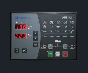
- The alarm output can be connected to a Gen-set controller for monitoring


